Sep 3, 2026Process
CNC Machining Tolerances Explained: ±0.005mm vs Standard — What They Mean and When You Need Them
What do ±0.005mm and standard tolerances really mean in CNC machining? How tight tolerances are achieved, measured and verified — and when you don't need them. A practical guide for engineers and buye
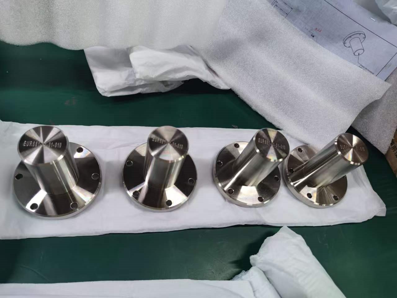
Every precision parts drawing carries a tolerance callout — but what does "±0.005mm" actually mean on the shop floor? How hard is it to hold? And is it even what your part needs?
This guide explains precision tolerances in practical terms: what they mean, how they are achieved and verified in CNC machining, and how to avoid paying for precision you don't need.
What does ±0.005mm actually mean?
Tolerances in CNC machining usually fall into two practical bands:
- Standard tolerance: ±0.01mm to ±0.05mm — the everyday machining band for most functional parts
- High precision: up to ±0.005mm, depending on geometry — the band for critical fits and sealing or locating surfaces
For scale: ±0.005mm is roughly one-twentieth of the thickness of a sheet of printer paper. It is the width of a machining mark, not a visible feature — which is exactly why it must be measured, not eyeballed.
When a factory advertises "±0.005mm," the real question is not the number — it's which machines, which measuring equipment, and which inspection reports back up the claim.
Do you actually need high precision? A keep-it-cheap rule
Tighter tolerances cost more: slower feeds, extra setups, more measurement cycles, and more rejected parts. The practical engineering rule is: specify tightness where function demands it, and stay in the standard band everywhere else.
Typical high-precision areas:
- Bearing journals, bushings and press-fit interfaces
- Sealing faces and O-ring grooves
- Locating features (pins, dowels, reference surfaces)
- Optical mounts and alignment features
Typical standard-band areas:
- General body dimensions, cosmetic housings and covers
- Non-functional spacing and clearance features
Every surface you move from "high precision" to "standard" reduces cost and lead time without touching performance.
From the drawing to the cutting edge: how tight tolerance is actually achieved
High precision is a production system, not a single machine setting. The load-bearing elements:
1. The right machine tools. High precision calls for stable machines — CNC turning and milling centers, 5-axis machining and Swiss lathe machining for small, long or complex parts, with grinding available where surface conditions demand it.
2. The right cutting strategy. Finishing passes with light stock removal, controlled tooling and stable workholding keep thermal and vibration error inside the tolerance band. This is where experience and machine selection matters more than the nominal number on the quote.
3. A stable environment. Thermal expansion is the quiet enemy of tight tolerances — a few degrees of temperature drift moves metal enough to matter. Serious precision shops control shop temperature during machining of critical tolerances.
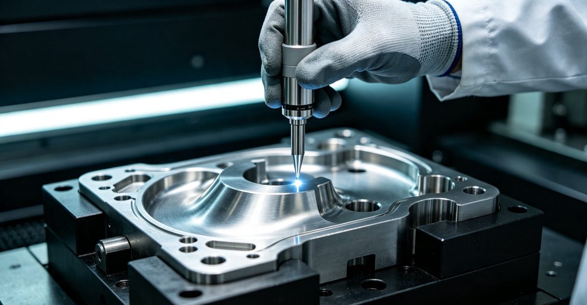
4. Measurement, not assumption. A precision tolerance is only real if it is read back with proper metrology. Expect a Coordinate Measuring Machine (CMM), a First Article Inspection (FAI) report, and 100% inspection before shipment on critical parts — with the report data, not just a "we checked" claim.
Tolerance is a contract: put it on the drawing
- Call out tolerances on functional features only, with clear datum references (GD&T) — not on every dimension
- Specify the measuring reference points so the shop and inspector agree on what is being measured
- Tell the factory where the need is critical (sealing, fit, alignment) and where it isn't
- Send STEP/IGES or native CAD files plus a 2D drawing (PDF/DWG/DXF) — 3D geometry without the drawing leaves tolerance intent ambiguous
When both sides agree on what "precision" means on your drawing, the inspection report becomes a real verification contract instead of a formality.
What your quote should show
A factory with real precision capability will respond with:
- A Design for Manufacturability (DFM) review commenting directly on your tolerances — flagging expensive ones and suggesting cheaper alternatives
- Different price/lead-time expectations for standard versus high-precision zones
- The inspection plan (FAI, CMM, CoC with material certificates)
Your part feature | Suggested tolerance band |
|---|---|
Bearing journals, press-fit, sealing faces, locating surfaces | High precision: up to ±0.005mm (geometry permitting) |
General functional surfaces, assembly clearances | Standard: ±0.01mm to ±0.05mm |
Cosmetic housings, non-functional dimensions | Standard band; can usually be opened up further |
Your next step
Send your CAD files for a free DFM review to a precision machining factory that documents what it does — for example, Idar Tech in Dongguan, China (ISO 9001:2015, tolerances to ±0.005mm, CMM/FAI reports with 100% inspection). You will get a transparent itemized quote within 24 hours, with an honest read on which tolerances your part really needs.